Safety information
Ensure the chaser bin is on level ground and that your team are using appropriate PPE. You may need to adjust part of this procedure to suit your working conditions. Consult your Davimac Group Relationship Manager if you are unsure about any part of this procedure.
Grease nipples require four pumps of grease per 50 hours of operation. The safest way to grease the bearings is to slowly spin the augers by hand.
Do not attempt to grease rotating augers using your tractor's PTO.
Recommended time
You should set aside 6-8 hours to fully complete this job.
Tools required
- Chaser bin parts manual
- 6 x UCF210 bearings and covers (456-2010)
- 1 x UCF313 bearing (680-2035)
- 1 x UC215 bearing (680-2136)
- 6 x M6 grease nipples
- 1 x M8 grease nipple
- Standard sockets and spanners
- Allan key set: 3-6mm
- Large three-prong gear puller
- Oxy heating kit
- Amery paper
- Thread locker
- Grease gun
- 2.5t strap or come along
- Forklift to the lower gearbox or various stands and jacks
- Pliers
Inspect and replace PTO shaft bearings
Remove the front PTO shaft.
Remove the 6 M12 bolts securing the bearing cover guard (680-4309).
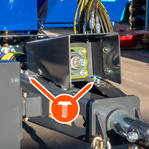
Undo the 4 16mm bolts holding both UCF210 bearings to the PTO bracket (680-4308). Loosen both M6 grub screws that secure the bearings to the PTO drive spline (680-3039).
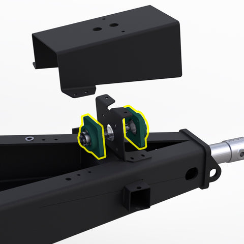
Pull off both front and rear bearings and replace if required. If the bearings are in good condition do not replace them.
Turn the housing so the grease nipple is in the upright position. If a grease nipple is not fitted, please remove the grub screw and fit 2 M6 grease nipples.
To refit, secure the PTO drive spline, the PTO bracket, and then the bearing cover guard. Don't forget to apply thread locker both grub screws securing the bearings to the PTO drive spline.
Inspect and replace the rear cross-auger bearing
Inspect the rear cross auger bearing to ensure the grease nipple is in the upright or lower position. If a grub screw is not fitted please remove the grub screw and fit the M6 grease nipple.
If the bearing housing needs to be rotated, you will need to use a 2.5T ratchet strap or wire rope come along to do the following:
- Remove bearing cover (0207020-05)
- Support the cross auger by suspending it from the most rearward tarp bow
Do not wrap the strap over the flighting. You may need to spin the augers to allow the strap to be wrapped around the auger tube directly below the tarp bow.
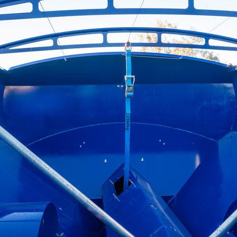
Take the weight of the auger and remove the 4 bolts from the UCF210 housing that are mounted on the auger end plate (0207308-04). Spin the 210 bearing housing or replace if the bearing needs replacement, and place the grease nipple facing up.
To refit, carry out the procedure in reverse.
Inspect and replace bottom auger gearbox bearing
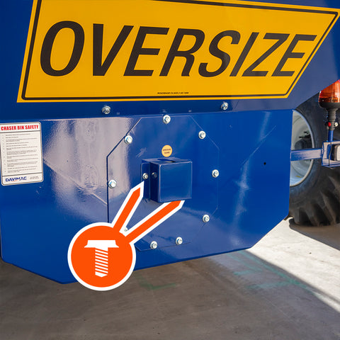
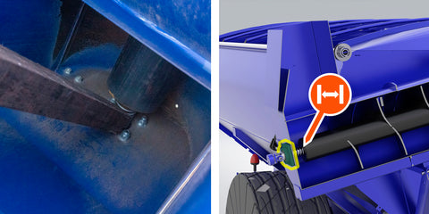
Check the bottom gearbox bearing (680-2035) to assess its condition and to see that it has a grease nipple fitted. If it is absent or damaged replace it with a straight or right-angled M8 grease nipple.
If the bearing requires replacement you will need to drop down the gearbox and mounting plate. (0207025). You do not need to remove the gearbox from the mounting plate.

Inspection and replacement of the cross auger front shaft bearings.
Inspect the front cross auger shaft bearings. If the bearings are in good condition you will need to remove the grub screws and fit grease nipples if required. If the bearings are in need of replacement, please follow the below steps.
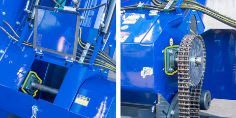
Loosen chain tensioner, remove the drive chain. You will then need to remove the taper lock (202-0098 Locking Assembly Z6-50X80) from the drive sprocket (0207087). You will need to remove all bolts, fit 3 or 4 bolts to the front taper lock, loosen and remove the front piece.
Then place 4 bolts into the front of the centre locator and tighten. This will push the rear taper lock backwards. You may need to use a small amount of heat on the rear of the sprocket (0207087).
Once this is done, you will then need to spin the cross auger into a position and use a 30mm socket and spanner to remove the locking bolt that secures the front driveshaft to the cross auger. Secure the front of the auger to the tarp bow in the same process used on the rear bearing inspection on the cross auger. Take a slight amount of weight.
Once the locking bolt has been removed you will then need to remove the bearing locking grub screws from the drive shaft (0207095) on both UCF 210 bearings. Slide of the front bearing behind the drive sprocket by undoing the 4 x 16mm bolts and pulling towards the front of the bin.
After the front bearing is off you will need to slide the front driveshaft towards the front of the bin. The cross auger will need to be in the central position to get the shaft past the second bearing mounting bracket.
Pull the shaft out of the bottom auger top inspection cover. Replace both bearings if required, fit grease nipples. Carry out the procedure in reverse to refit.
Remember to fit Loctite to all grub screws.
When fitting the to drive sprocket please ensure when the taper lock is refit that the chain runs parallel to the bottom drive sprocket, you will require a straight edge to check this.
Refit chain and tension as required. Ensure chain tension bolts are tight.
Inspect and replace the bottom auger centralising device
To replace the bottom auger upper centralising bearing (680-2136), remove all mounting bolts from centralising device (0207135), remove the M12 auger locating pin, and fit a plain bolt into the location. You will require a large 3 prong gear puller to remove this device.
Ensure all rust and paint is removed from the shaft prior to attempting to pull this off, it is a tight fit.
Replace bearing are required with new bearing and refit device back to the shaft, secure all mounting bolts and refit auger locating pin.
Inspect and replace the top auger bearing
Inspect bearing for wear and fit a grease nipple if required. If the bearing requires replacing follow the below steps.

Lower the top auger down into the transport position. Push the top auger up until it is resting on the external bolt. Place a piece of timber between the auger and auger housing to prevent to auger from sliding out and lower the auger onto the timber.
Remove the external locking bolt and the four 16mm bolts that hold the bearing to the auger frame. Please note there is a spring behind this cover which will have a small amount of stored energy in it. Replace bearing as required and refit, tightening all mounting bolts.
Do not fit grub screws to this bearing as the top auger is designed to slide in the housing.
Refit the external locking bolt to stop the auger from falling out when lifted into the unload position.
Remove the timber from inside the auger.